In this chapter you find examples of damageswear patterns or indications on the shaft seal ,which provide you information in which area you need to investigate to solve the situation.  On request we offer a shaft seal inspection to support you with solutions. You receive a full inspection report from your damaged seal.

One of the most common  causes of  seal failure:

By refrigeration compressors is the single shaft seal arrangement the most used.  The shaft seal is build in the housing of the compressor and contains a rotary – and stationary part . The sealing has been completed by the liquid ( oil and refrigerant mixture) between these parts. The most engineers do not realize that by refrigeration compressors always  the  Lubrication oil contains a part of the refrigerant.  The amount of refrigerant is depending  on pressure , refrigerant, oil characteristic  and temperature.  The mixture of oil/ refrigerant enters the lubrication system and start collect heat – the liquid refridegassinggerant start to boil-off and due to little higher pressure –  it will De-gas in seconds and after  fresh  mixture enters the shaft seal .  The process restart it`s selfcooling takes more time than heating up —  so we can face at the end  : dry running of the shaft -seal in liquid bath

The  Pusher type  shaft seal arrangement 

The Pusher type seal is one on the oldest seal types in refrigeration compressor . 

One was a discussion regarding the O-rings  – by a pusher type the O-ring have a dynamic functionswelling can let the shaft seal  lock in open positon .  By the use of high quality of   elastomers , there is no problem today . 

There is for the users still a big benefit – pushertype seal are easy to repair – even the change to a higher Quality of carbon binder combination is possible,


The bellow type shaft seal arrangement

Today we find  the bellow type shaft seal .  The O-ring has only the function to seal between the metal of shaft seal and the shaftmore swelling  more tightness ( with in limits). All movements  increase speed and reducing speed , force to stationary ring must be captured by the bellow.  these types are not easy to restore only lapping till the carbon/ binder of sic is without the limits. 

Wear rings : basic in the refrigeration industry  we use  two kinds of wearings material:  carbon/ binder material of SIC ( which is basic glass) 

In the old days we use a very stable material to bed the carbon in. it was antimony – basic it was standard in the Industry – today these shaft seal are only on special order Our COLDORES HR -heat reducing is one of them.  antimony is heavy metal and in the most shaft seals replaced by a resin as binder

Resin is available many combinations . Resin has no self lubrication effects. The generation heat by friction is also the key for Degassing of lubrication oil.  The generated heat will be longer captured    in the resin/ carbon wear ring of the seal. Benefit is  a resin carbon wear ring, which can be more stable as SIC material against vibration

Antimony is  more stable than resin- It reduces the generated heat form the  seal to the media . Hotspots will be minimized .

down-side : due to the used on heavy material the seals have longer production time

Silicon carbide is carbon and silicon  ( SIC) basic glass.  Basic a very good solution if the  media contains hard partialsSIC is very hard materialsvery good heat conduction – however using a O-ring direct behind the SIC ring can burn the O-ring. 

Good heat conduction – down side in all directions

Very hard material: ideal for a media with hard partials  – in Refrigeration compressors we have not this situation.

chemical stable : basic  our acid  is low in refrigeration compressors.

SIC is basic glas – the edges are very fragile – best solution  SIC ring in bedded in metal. 

Sic is glass , however like glass a thermo shock it will be damaged.   small partials of glass will be forced through the compressor .

Sic is weak for vibration so critical Frequencies as more risk for the shaft seal 


Degassing damage and how to recognize  

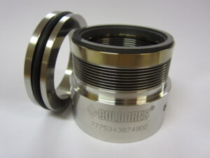
    If we look at a  damaged shaft seal we see at first only a  small damage. but if you look closer teh more you find .

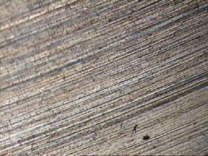
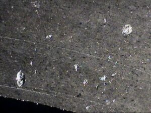
  more small damages like very small explosions   

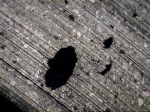
We find  interesting shapes separate at the top from each other bit stil in almost the same area

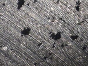
This indicates that small  explosions  caused the first put  in the wear material – not mechanical  but by degassing  of the lubrication oil. 

Blistering, Dry-running :

Caused by :  the lubrication oil contains a higher proportion refrigerant ( liquid phase).  The refrigerant will be forced to go into gas phase because of the heat developed by the Shaft seal. (Heat of friction between stationary- and rotating part.

The pressure of the refrigerant will light rise above the lubrication pressure only for a short moment and force out the lubrication film. The dry-running take place. Fresh oil enters the shaft seal and  the proces restarts – only  heating-up is always faster than cooling down – cooling down  will take longer. In reality the  temperature will become higher at local spots and the proces accumulated

The discharge temperature is important for limited account of Liquid refrigerant.  

Refrigerant

Recommended temperature area

Extern isolation and  heating recommended by standard unit

NH3

73-80°C

no

R22

67-72°C

In some cases by external air flow

R404A

67-72°C

Some times

R507

67-72°C

yes

R422D

67-72°C

yes

Adjusting of the  injected oil temperature  by screw compressors

In each screw compressor unit is an oil separator included.

For the best performance of an oil separator there are a checking procedure based on the balance between the required electric energy and the required compressor power on the shaft.


80% of all compressor units are misadjusted. In 90% of the cases the adjustment is out side the tolerances, leading to excessive wear on compressor parts, higher energy consumption and oil carry over.


We strongly recommend using a logging over a time period or taking the time for the adjustment.

Creating the balance needs time by compressor unit with more than 100Ltr. of lubrication oil.


The most compressor units are suited with a separate oil injection line to control the discharge temperature. The recommended Discharge temperature is dominated by the used refrigerant.

The recommend discharge temperature: The temperature area , where the adhesion is the lowest between oil and the refrigerant.


.

Note:

For the best results – take your time and let the compressor run stable at same load.

By Frequency drive units run at the same speed.

By fixed drive speed units with Eco : test by a higher slide position as 80% with ECO.

reaching the recommended oil separator entry temperature:


  • Install a amp meter on the E-motor.( the best is a digital logging)
  • Install pressure transmitter behind and before the oil separator elements and log the difference pressure.
  • Install a discharge temperature transmitter.
  • Run de compressor unit without limited the waterflow to the oil cooler at fixed load.
  • Read the discharge temperature and amperage after 30 min.
  • Limited partly the oil flow for the rotor injection – notice if the discharge temperature is increasing and the amperage is decreasing – lead time 2 hours.
  • Is the recommended oil temperate reached? If not :close the main oil injection valve more. Wait for the changes at least 1 hour.
  • Follow these steps, till the moment the amperage balance. The procedure take time some times 2 days, due to the fact not all oil is passing the compressor.
  • If the amperage is stable for 4 hour under the same conditions, finalize the discharge temperature wit external control systems.

Look is the difference temperature of the oil separator is not stable. This could indicate defects to the oil separator elements or damaged gaskets